8x8x8 RGB LED Cube - Part Two
April 04, 2021
In Part 1 I built a base board that allows controlling an individual LED level in the cube using TI LED driver ICs, which allow the LED cathodes to each be lit to just under 20mA with the resistor value chosen for the drivers.
The problem with this is that it only allows you to combine red, green, blue at their full brightness to make colors. For a wider gamut of colors we need to be able to contribute each color at a lesser brightness. Preferably using 8 bits per color, allowing us to use standard 24 bit color when programming.
Pulse Width Modulation
Normally when controlling LEDs with a microcontroller, you can use pulse width modulation (PWM) on supported IO pins. With PWM on an Arduino for example, you can specify a value from 0-255, and the controller itself will handle cycling voltage on the pin to match the value provided.
Bit Angle Modulation
Each increasing position in a binary number represents a doubling of the amount of bits it represents. If we chose 8-bit angle modulation for example, we can represent 256 numbers, 0-255. If we consider a unit of time, we can divide it into 256 ticks, and we can allocate an amount of ticks corresponding to the significance of each bit position. When a number is presented, we can go bit-by-bit, increasing in significance, and if that digit is a 1, then its proportion of ticks is held high, or if the digit is 0, its proportion of ticks is held low.
The example waveform below is for 4-bit angle modulation. A unit of time is divided into 16 ticks, and the “earlier” ticks for this bit angle frame are for the proportion of ticks reserved for the least signifant bit (bit 0).
Controlling the Cube
PWM wouldn’t work for our use case, as we cannot cycle the output on the data lines, as the LED drivers expect serial input, and the drivers would interpret the cycles as binary data for each of the LEDS. BAM solves for this by allowing us to think about each bit position separatly.
Remember that we can only have a single level on at a time, and to complete a frame, we cycle all the levels within that frame.
When talking about a frame for the cube, it’s a buffer of 1536 8 bit integers, 512 LEDs multiplied by 3 colors, representing the brightness each cathode should be. Each triplet in the buffer is the GRB color. The GRB color is stored as thats the physical ordering of the LEDs and it’s easier to store in that order instead of the common RGB.
Given the buffer, when we write out a level, we know the color we want, but we can only turn each color in each LED on or off.
This is wear BAM comes into play, instead of writing out each level (8 of them) to complete a frame, we now have to write out each level at each bit angle. These 64 level writes when completed make up a frame, and visually would equate to roughly the color intensity we wish to achieve.
The period between bit angles will be determined by the proportion of an allocated amount of time that the bit we are writing represents. If we wrote out each level for all the bit angles, then moved on to the next level, that would be too much time between levels. Instead, we can write out every level at the current bit angle for every level, then increment the bit angle. In other words, the entire cube will be lit for every bit at the current bit angle, and we cycle up the bit angles. The completion of liting the cube at each of the bit angles completes an entire frame.
bitPosition = 0
while(1):
  for level in levels:
    setOEHigh()
    turnAnodesOnFor(level)
    for color in cubeFrame[level]:
      // If the color has a bit in this position, we turn the cathode on.
      write(color & (0b00000001 << bitPosition))
      pulseClk()
    pulseLE()
    setOELow()
    waitProportionalTo(bitPosition)
  bitPosition === 7 ? bitPosition = 0 : bitPosition += 1
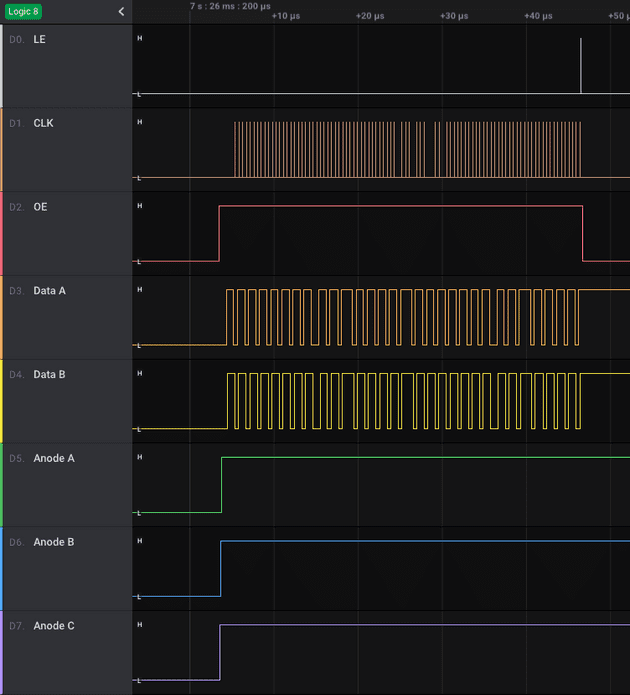
Figure 1 is a capture from a logic analyzer of the controller output for a single level write (level 7). This would be for a single bit angle for this level.

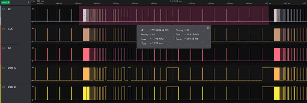
Figure 2 is zoomed out from Figure 1, and shows a complete frame being written. There are 64 rising edges on LE, indicating 64 complete writes of a full levels worth of data. This is from the 8 levels * 8 writes needs for BAM.
You can see after writing out an entire cube’s level, every 8 LE pulses, the time between LE pulses gets longer and longer. The later stage of a frame leaving the colors displaying for longer, representing the most significant bits in the colors being displayed.
In order to determine how long the pause between writing each level, we need to determine what our target frame rate will be. In figures 1 and 2, I had set it at 10FPS, and the timing of each entire frame write is given 100ms. Knowing that we have to write a whole frame in 100ms allows to divide the BAM ticks up accordingly. I talk about how to divide up each frame in the next section.
This demo shows the rendering process while the cube is rendering a single frame. In realtime, the cube is rendering a solid color, but slowed down, you see the modulation happening. What’s interesting is that a single perceived color can actually be made up of multiple colors displayed for the varying times.
| Bit # | R | G | B | Output |
| 0✔️ | 10101011 | 00010100 | 10011110 | |
| 1 | 10101011 | 00010100 | 10011110 | |
| 2 | 10101011 | 00010100 | 10011110 | |
| 3 | 10101011 | 00010100 | 10011110 | |
| 4 | 10101011 | 00010100 | 10011110 | |
| 5 | 10101011 | 00010100 | 10011110 | |
| 6 | 10101011 | 00010100 | 10011110 | |
| 7 | 10101011 | 00010100 | 10011110 |
The Microcontroller
I am using an STM32F446 microntroller, it has 512 Kbytes of flash memory, and 128 Kbytes of SRAM. I found the STM32 lineup’s tooling, IDE, and documentation to be better than the ESP32 chips I have previously used, although I do lose WiFi. In the STM32 lineup the STM32F446 supports a faster clock rate of 180Mhz (using an external 8Mhz oscillator, the dev boards have one on them already), and the Nucleo development boards for this cheap are easily avaialable on Amazon. I thought the faster clock would be beneficial to achieving higher frame rates while still being able to calculate animations between frames.

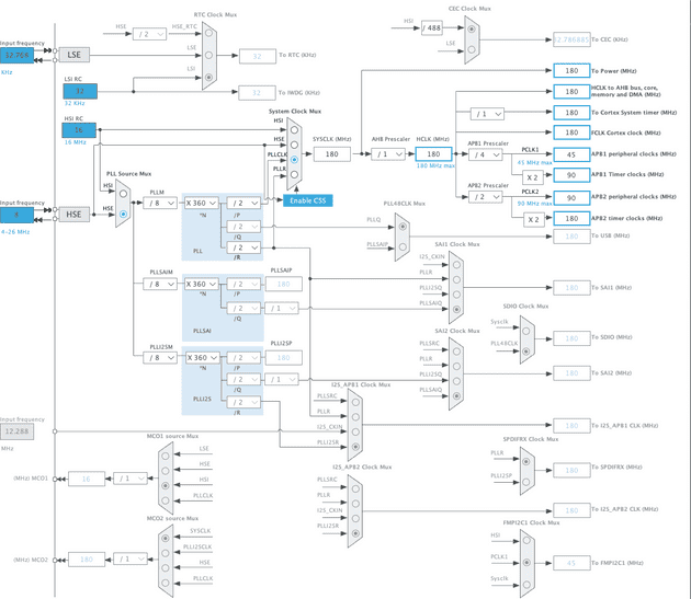
The STM32 has various configurable timers, which will be used in count-up mode. When a counter reaches a configured value, an interrupt occurs. The counters run on a clock source that depends on which timer is being used, TIM2, which I’m using to drive the LEDs for BAM, runs from a clock source of 90Mhz. In Figure 3, this is the APB1 timer clock. The data sheet says this timer can run at 180Mhz, but I can’t figure out how to configure that, and 90Mhz will do.
The timers have two stages, a prescaler (16 bits for TIM2) and an autoreload counter (32 bits for TIM2). The prescaler is how many ticks of the clock source are needed before it triggers an increment in the autoreload counter. When the auto reload counter hits its target, it causes an interrupt, and the counter is set back to 0 and starts again. This interrupt is where we write one of the levels worth of data.
The prescaler value for the timer can be determined from our desired frame rate.
targetFps = 250
// ticks per bit angle
  0b00000001 // least significant
  0b00000010
  0b00000100
  0b00001000
  0b00010000
  0b00100000
  0b01000000
+ 0b10000000 // most significant
-------------
ticks per BAM cycle = 2040

clock = 90,000,000 // hz
prescaler = 90,000,000 / (2040 * targetFps) = 176
By setting the prescaler to 176 as calculated, our auto reload register is now incrementing for every single bit angle tick at the speed we need to achieve the desired FPS.
Now, in the pseudo code in the above section, waitProportionalTo(bitPosition) sets the auto reload counter to the number of ticks for the next bit angle position (0b00000001 << bitPosition), causing the counter to act as the timer for when the next write should happen. The timer auto reloads and runs continually, so the timer acts as the never ending while loop. This code runs anaologous to a spearate thread that continually writes what is in the active frame buffer to the cube.
The main() function of the program runs a continous while loop that runs a function called looper() in each effect. The effect when initialized is given a speed, which is the target amount of milliseconds that a new frame in its animation should be updated. The looper function will just return if that time has not passed yet. When the effect is calculating and updating the cube for the next frame in its animation, the controller is still possibly interrupting that code in order to write a level in the cube. The possible interruption while an effect is writing out its next animation frame poses the problem that the cube could be writting out half updated frames, resulting in a tearing effect. In order to avoid this, two frame buffers are kept, an active and inactive. The effect first writes out to the inactive buffer, and only when it’s complete, it commits it by swapping with the active buffer. The LED driving logic only ever runs off the active buffer.

I prototyped the controller board on the Nucleo dev board, so there are pinouts configured for debugging, as well as an SPI interface that made it into the final PCB. I thought I could use maybe to add blueooth or WIFI through the ribbon cable. The final board is based on the applications notes from ST.
The base board has a ribbon cable connector and a header, both can control the board. The ribbon cable was easier to hook up to the dev board, but the header makes it easy to clip on the final PCB controller to the cube base. The ribbon cable connector on the controller PCB however is for hooking up to the STLINK programmer to flash the programs on it, as well as using the debugger. It also has an SPI bus available for any future expansion or communication with the PCB.
Up next, I will post the controller code.
